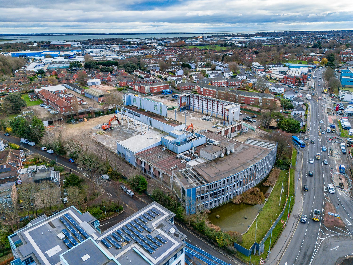
Print Works, Portsmouth
Hughes and Salvidge commenced the demolition works to the former Print Works in Portsmouth in August 2023. This is a current project for Hughes and Salvidge.
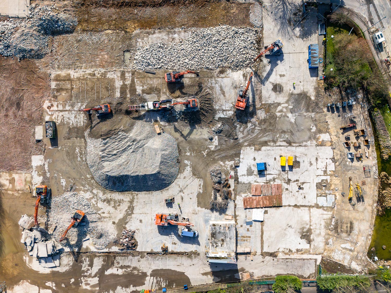
The scope of works included:
- Isolation of incoming services.
- Conducting an R&D survey.
- Removing all asbestos found on the R&D survey.
- Retaining of assets, including the triple monolith monument to the front of the site and the ‘NEWS’ wall mounted mosaics installed to the external concrete frame of the first floor of the curved building.
- Demolition of all structures above and below ground.
- Crushing of all arisings to 6F2 and providing certificates.
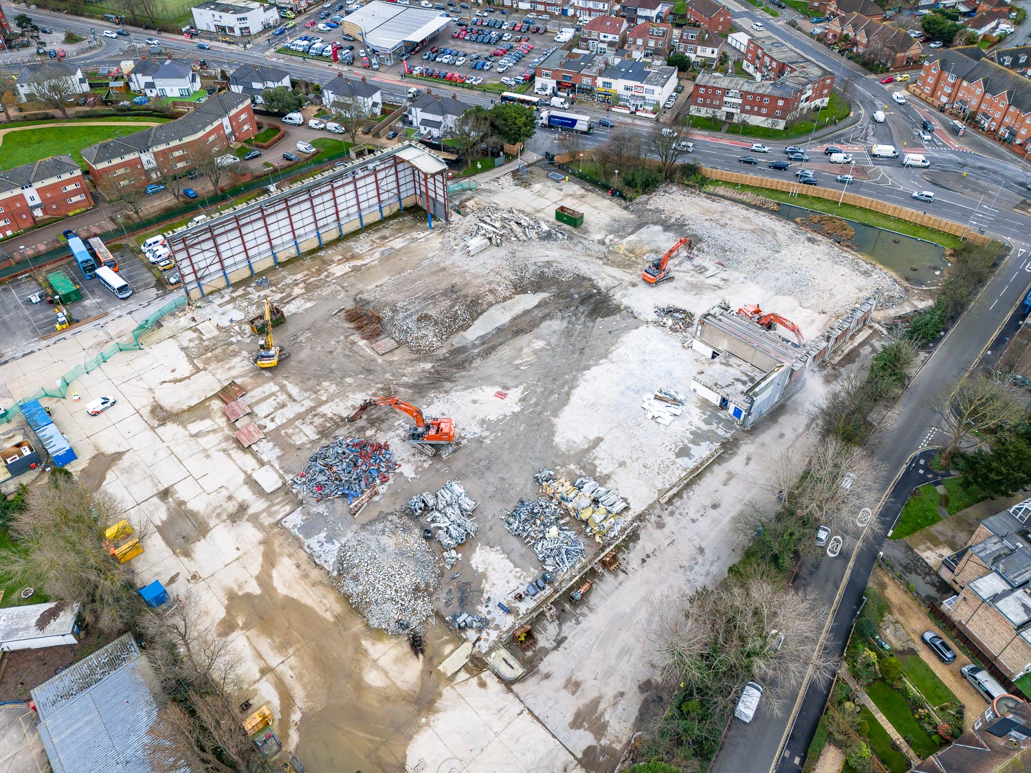
- Protection of the pond at the front of the site.
- Removal of all obstructions down to 1.5m.
- Cropping of existing piles to 1.5m.
- Installation of new hoarding to front of the site and palisade fencing.
- Protection of trees.
The 22-week project had multiple site restrictions to consider ahead of commencing work. A live MOD sewer line ran though the site and required protection throughout. First Bus required access to an area to park their buses. We liaised with First Bus throughout the project to ensure they had the access/egress and space required every day of the project. The Print Works are/were situated in close proximity to residential housing. In person and video call resident meetings were conducted ahead of the project beginning, and newsletter and leaflets with essential information were provided to all residents in the local area. Consideration was given to residents at all times with no plant work beginning until after 8am and ceasing ahead of 6pm.
Hughes and Salvidge utilised M&E subcontractors from our approved supply chain to locate and isolate all services back to the boundary and/or the London Road substation.
There were live drainage systems known across the site that were protected with silt and sediment traps and covered by steel road plates to prevent collapse.
The live transformer situated in the last bay of the warehouse was protected and this bay was able to stand independent while we demolished around it.
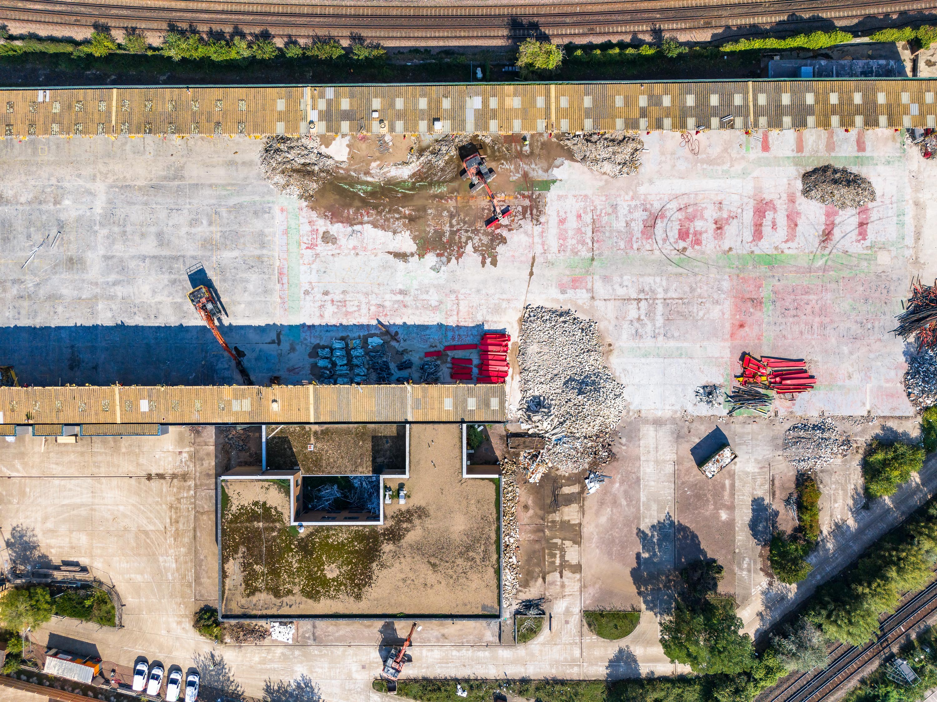
A pontoon was erected in the pond, and ply installed on top to prevent any debris falling into the pond during demolition.
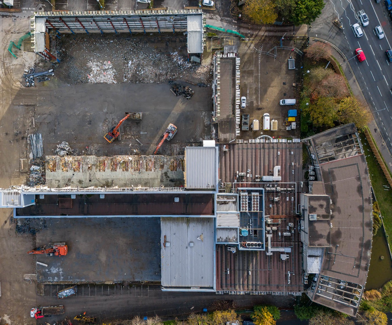
Phase 1 – Removal of the loading bay
The loading bay consisted of a steel frame makeup with a metal clad roofing structure.
The machine worked from the southern elevation, fitted with a rotational shear attachment, shearing the first truss adjacent to the eaves haunch of the first column, followed by the alternate end of the steel, allowing the truss to lower. The machine then peeled away the roof coverings and set it aside, exposing the purlins and associated tie braces.
The machine sheared the purlins, isolating the first truss, allowing it to fall to ground level.
The machine then sheared the column as close to the ground as possible, cutting and folding the column to the ground.
The same process was followed, working from south to north, until the loading bay was demolished in its entirety.
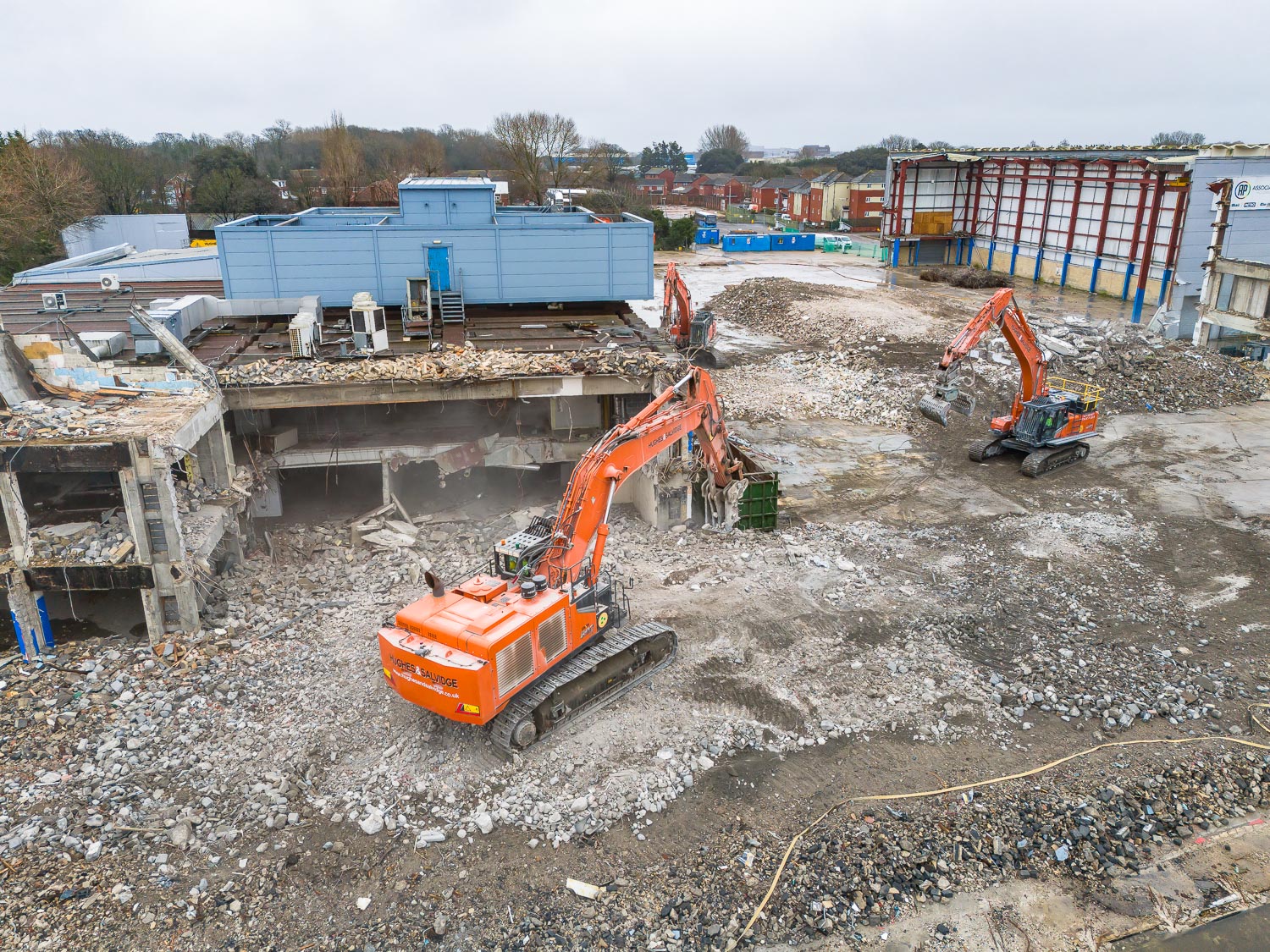
Phase 2 - Warehouse 1
- The structure consisted of a steel frame, adjoining to the main printworks structure, clad with metal sheeting and low-level glazing panels.
- The machine commenced from the eastern elevation, stripping the cladding panels from the gable end, setting them aside, and removing the associated cladding rails.
- The machine sheared the northernmost truss, adjacent to the column, freeing the truss.
- The truss was sheared as close to the main, high-level, print works structure as possible, forming a separation between the first bay and the adjacent structure.
- It was then lowered to access the roof makeup.
- The roof sheeting was removed and the purlins sheared to lower the truss to ground.
- The column on the northern elevation was sheared at ground level and lowered into the confines of the structure.
- With the first bay complete, the machine removed the remainder of the bays up until the bay associated with the live services.
- The final bay was left in situ, along with the associated internal walls and roof structure. Warning signage was erected on Heras fence panels, providing a statement of live services above and below ground.
Phase 3 – Intermediate warehouse structure
- This structure was also steel framed, with a concrete roof and a steel framed, fixed, lean-to structure.
- The machine commenced from the eastern elevation, removing the steel frame lean-to.
- The operator removed the cladding sheets from the roof structure, exposing the makeup of the steel frame. They then worked south to north, separating each bay between the columns, reducing the lean-to to ground level for each bay. The column was then cut flush with ground.
- The process for the lean-to was repeated until the structure was removed in its entirety.
- The machine then removed the roller shutter doors and the front façade of the gable end from the main structure. The arisings were segregated into their relevant waste streams as the works progressed.
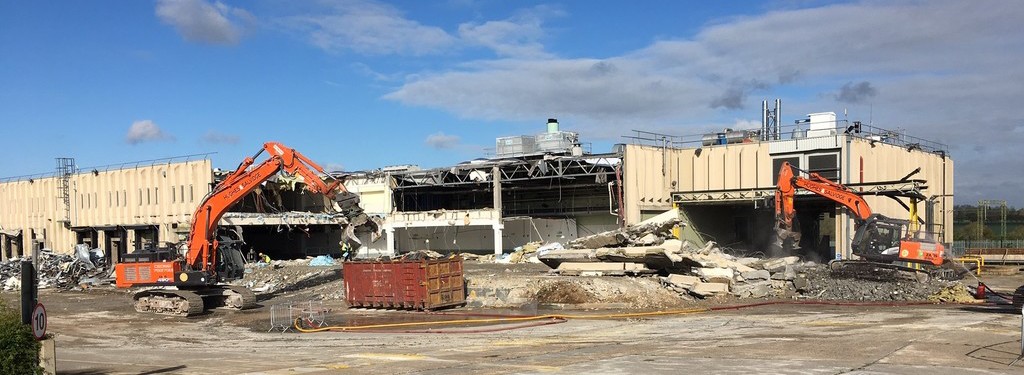
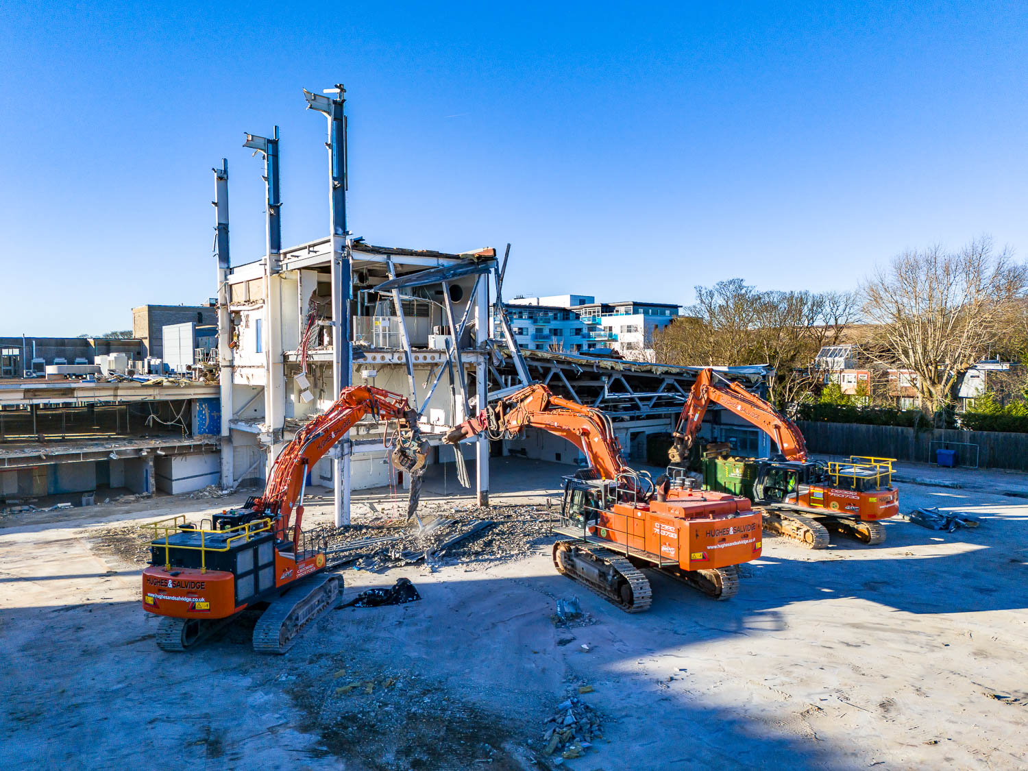
Phase 4 - High-level warehouse structure/printing press
- The high-level warehouse/printing press structure was constructed of a steel-frame makeup, metal clad, a multitude of presses and equipment and a mezzanine floor.
- The machine began by peeling the cladding sheets away from the structure in a controlled manner, lowering them to ground level for the secondary machine to stockpile.
- A section of the roof cladding was removed back to the second bay and the machine then worked from the top down, removing the associated cladding rails, tie braces and intermediate steel beams. The machine worked down the front façade of the structure, exposing the printing press and other plant, releasing the mezzanine floor section from around the first press and lowering it to ground level.
- The operator then sheared the fixing points of the press and the associated equipment, allowing the press to be removed from the structure as a whole unit.
- This process shall be repeated until the structure is demolished in its entirety.
Phase 5 - Low-level office block
- The structure comprised of a steel frame, with a concrete roof.
- The machine removed the glazing and the front façade of the gable end.
- Once the makeup of the structure was exposed, the machine began to isolate each cross member of the structure, shearing the steel adjacent to each column on either side of the building, and lowering them into the footprint of the structure. This allowed the concrete roof to lower into the structure.
- The intermediate columns were sheared to provide access within the footprint, leaving the columns associated with the two adjacent buildings in situ.
Phase 6 – Main office block
The main office block was three-storey reinforced concrete structure, adjacent to the pond.
Phase 7 – Storage Unit
The storage unit was steel framed with metal clad to all elevations. Our high-reach excavator fitted with a rotational shear attachment worked from the eastern gable, removing the cladding sheets and setting them down at ground level for the secondary machine to process. The machine removed a section of the roof within the first bay, setting aside the arisings. It then removed the uppermost cross member, followed by the intermediate horizontal steels, and then the supporting columns associated with the uppermost level. The intermediate floor was then removed and pushed through onto ground level, also cleared by the secondary machine. The lower bay was removed in the same manner.