Demolition and Dismantle of the Polystyrene Unit - Kingdom of Saudi Arabia
Hughes and Salvidge were appointed Principal Contractor for the demolition and dismantling of S-Chem Polystyrene Production Plant in Al Jubail, Kingdom of Saudi Arabia in the last quarter of 2023.
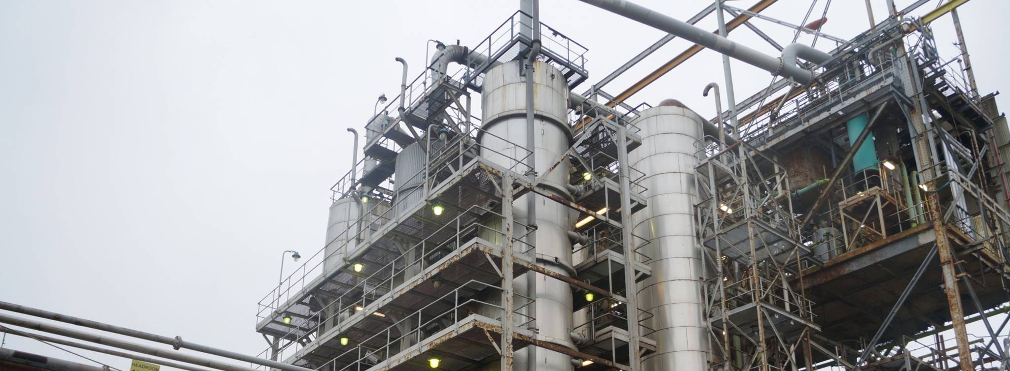
With 6 areas, the project was bordered by a live substation and sump system, a live main site pipe rack and by the live Teal plant and ground flares, with sections also adjacent to a live road to the wider S-Chem site.
Where practical, track mat and or road plates were installed to provide ground protection and safe positioning of the excavator. All live manholes in the area were covered with steel plates to avoid any damage to same.
All excavators worked while facing the structures being demolished/dismantled, positioned at a minimum distance by using 2:1 ration, so any falling debris dropped to ground level safely without incurring any danger to the plant operator.
All materials were segregated and processed by a dedicated excavator for environmental checks and subsequent processing.
Area 1 – Utilities
This area contained approximately half the length of the main Pipe rack, the Utilities, and the unit furnace and incinerator.
Works commenced with the separation of the pipe rack; a portal frame with steel framed upper section and concrete lower section. The separation was carried out following a scaffold screen being erected parallel to the live substation.
Operatives either cold cut the steel (via a recip saw) or unbolted each section, whilst a crane suspended the load. Operatives worked at waist height to ensure they weren’t below the load at any time.
Once separated the crane to lowered it to ground level. This operation was carried out on all horizontal beams working top down.
Area 2 - MRU-Hot Oil & Rubber Treaters
The demolition of the main process plant (Styrene Filters/Treaters, MRU, North-South Pipe rack, Rubber Syrup System) were carried out using high-reach excavators. Standard excavators were then employed for the lower-level works, including the dismantling of pipe bridges and smaller vessels, which were demolished on-site mechanically to expand the working area for high-level operations.
Area 3
This area consisted of the HIPS Line, GPPS Line, Central Piperack and Palletizer building. These 4 areas were split into phases to maintain safe control of the area.
The HIPS structure ranged from 3 to 5 storey, constructed of steel framed with fire protection coating up to halfway between the 3rd and 4th floors. The structure was 10m wide by 60m long by 17.7m high for floor 5 and 11.6m high for floor 3. Pipes span at varying heights along its full length.
The 1st floor contained various drums and heaters along with associated pipework.
On the 2nd floor were the bottom sections of the 70 ton reactors, along with various drums, vessels and associated pipework.
On the 3rd floor were the tops of the three reactors and two De-volitisation chambers, along with the De-volitisation Water Static Mixer, the Zinc Stearate Static Mixers, and manifold stations.
On the 4th floor there were three uninsulated Overhead Condensers, three agitator Package skids and three uninsulated air drums associated with the three reactors.
On the 5th floor were pipes and the continuation of the HIPS/GPPS Tubular Plug Flow Reactor Section 1. The top floor had some manifolds and the insulated HIPS/GPPS Tubular Plug Flow Reactor Section 2.
All of the above plant and equipment underwent enabling works allowing it to be safely removed by mechanical means, the equipment was either cut in situ using a rotational shear attachment or removed from its position whole to be processed at ground level.
Within the HIPS structure there were 4 vessels needing special attention;
- Prepoly Reactor
- First Stage Reactor
- Second Stage Reactor
- Tubular Plug Flow Reactor Section 1
The vessels were still removed mechanically, however we installed additional ground protection;
- Installed a protection area of rubber tyres at the base, then a 27mm steel plate on top of the tyres, and bulk timber (Ekki Mats) on top of the plate.
The demolition sequenced working top down, bay by bay. The structure was a steel portal frame with plant and equipment on all levels, with the reactors centrally within the bay. The reactors were hung from the top by 4 connection points which were bolted to two supporting steels that run between the bays. An excavator fitted with a rotational shear attachment began by removing the external cable tray and pipework from the face of the structure.
To ensure a safe and effective dismantling process, we positioned the 89T excavator securely on the south end of the pipe rack in a stable location with sufficient clearance for movement and reach.
The excavator cut away the pipework and associated equipment from the top of the reactor. We then removed the cross members at first and second floor level to allow us to remove any remaining obstructions around the reactor. This left the supporting steel in situ so the reactor was still secure.
The excavator then cut the supporting bracing in front of the vessel, before pulling the reactor from the framework onto the ground protection. As dismantled sections of pipelines and steel frame components accumulated, they were segregated into waste streams and loaded into waste haulage lorries.
The excavator tracked to the next set of bays to shear through the upper steel frame structure, allowing the displaced steel section to be carefully lowered onto the footprint of the pipe rack area.
This step-by-step procedure was followed while ensuring the stability of temporary retained structures to ensure a successful and responsible dismantling of overhead pipelines supported on the steel frame structure.
The GPPS Line was demolished the same way, and contained nearly the same equipment, so the procedure was followed with the installation of protection for the heavier reactors.
The GPPS Line had manifolds, pipework and small equipment running its entire length adjacent to the site boundary road. To ensure the boundary of site was protected this element of works was demolished bay by bay by a secondary excavator to allow full sight of the material during demolition.
The next phase was the demolition of the palletizer building, completely by mechanical means. An excavator fitted with a shear demolished the structure in a top-down sequence working bay by bay.
The structural report highlighted that the high-level support bracing should remain for as long as possible, for this reason we worked south to east as the bracing was located in the east and west elevations.
The excavator started by removing the cladding from the southern elevation, allowing the operator clear vision for the demolition of the roof section and internals of the structure.
The excavator removed internal equipment from the exposed floors before the floors themselves. The side elevations remained in situ as it included the wind bracing supports. Once exposed, the excavator carried out the same procedure with the back bay.
This methodology continued until the building was demolished to ground level, whilst keeping the structural stability during the works.
Area 4 - Dissolvers/Additives Building and Ancillary Plants
The rubber dissolvers building was a tall steel structure, containing loading machinery such as the Rubber Bale Loading Robot, Conveyor, Chopper, and Exhaust Blower. The 1st floor was dual-level, with a lower section featuring an electrical room.
The structure's northern section housed insulated Rubber Dissolvers spanning 4m dia x 10m high. Pumps had been removed, leaving concrete bases, pipework, and mixers and motors on top.
The warehouse was a steel-framed structure adjacent to the dissolver building, measuring 31m by 14/24m by 8m. It was fully clad and had a concrete block facility. The Additives structure was a 2-storey structure, 5m wide by 11m high by 47m long, with a steel-clad roof.
The first floor contained pumps, pipes, lifting beams, and an Initiator Feed Room. The top floor contained manifolds and filters. The Additives structure had additive tanks, carbon drums, and a connecting pipe rack to the HIPS/GPPS Lines in Area 3.
The structures were dismantled mainly by remote mechanical means. The works were organised to suit the demolition-phasing plan and involved small teams of demolition operatives/plant. These distinct stages were followed to achieve the above:
- Draining Residual Material-Incoming Pipe/Support from AREA 2 & 3
- Physical Separation Works-Incoming Pipe/Support from AREA 2 & 3
- Demolish structures by mechanical means
- Demolition of Concrete Bund/Upstands
Area 5 - Demolition & Dismantling of Tank Farm & Pipe Rack
This area contained product tanks pipe rack, the additive and mineral oil tanks, and the product and feed tanks. All the five tanks in this area had a layer of bit sand under the bases.
The size of redundant tanks demolished/dismantled in the area were:
- Styrene Tank: 10.7M Ø x 13.7m high
- Recovery Toluene Tank: 7.7m Ø x 11.9m high
- Mineral Oil Feed Tank: 7.7m Ø x 11.9m high
- Crude Distillate Tank: 12.2m Ø x 13.10m high
- Additive Feed Tank: 5.45m Ø x 10.4m high
- Pipelines, Racks and Structural Frame Support
- Ancillary Motors and Pumps
The tank demolition process followed the sequence below;
- Remove or strip tin corrugated sheeting and insulation
- Punch entry holes in the tank wall
- Shear and cuts down the tank wall progressively
- Shear through the roof structure from the eaves
- Dismantle and remove internal roof support
- Pull partly displaced section onto the tank footprint
- Shear and cut the tank progressively in a clockwise or anti-clockwise direction
- Separate demolition arisings into various waste streams and remove from site
- Progressively cut through and shearing the base of the tank.
- Remove scrap arising to a processing area
- Repeat the sequence until the tank is demolished
Area 6
The Peroxide Storage Building was approximately 17m long x 10m wide x 10m high and was made of steel frame construction with external sheet cladding. There was a live fire water feed we installed protection to by means of sand bags installed around the perimeter, ensuring that the clearance is a minimum of 150mm, before installing 20mm steel plate on top.